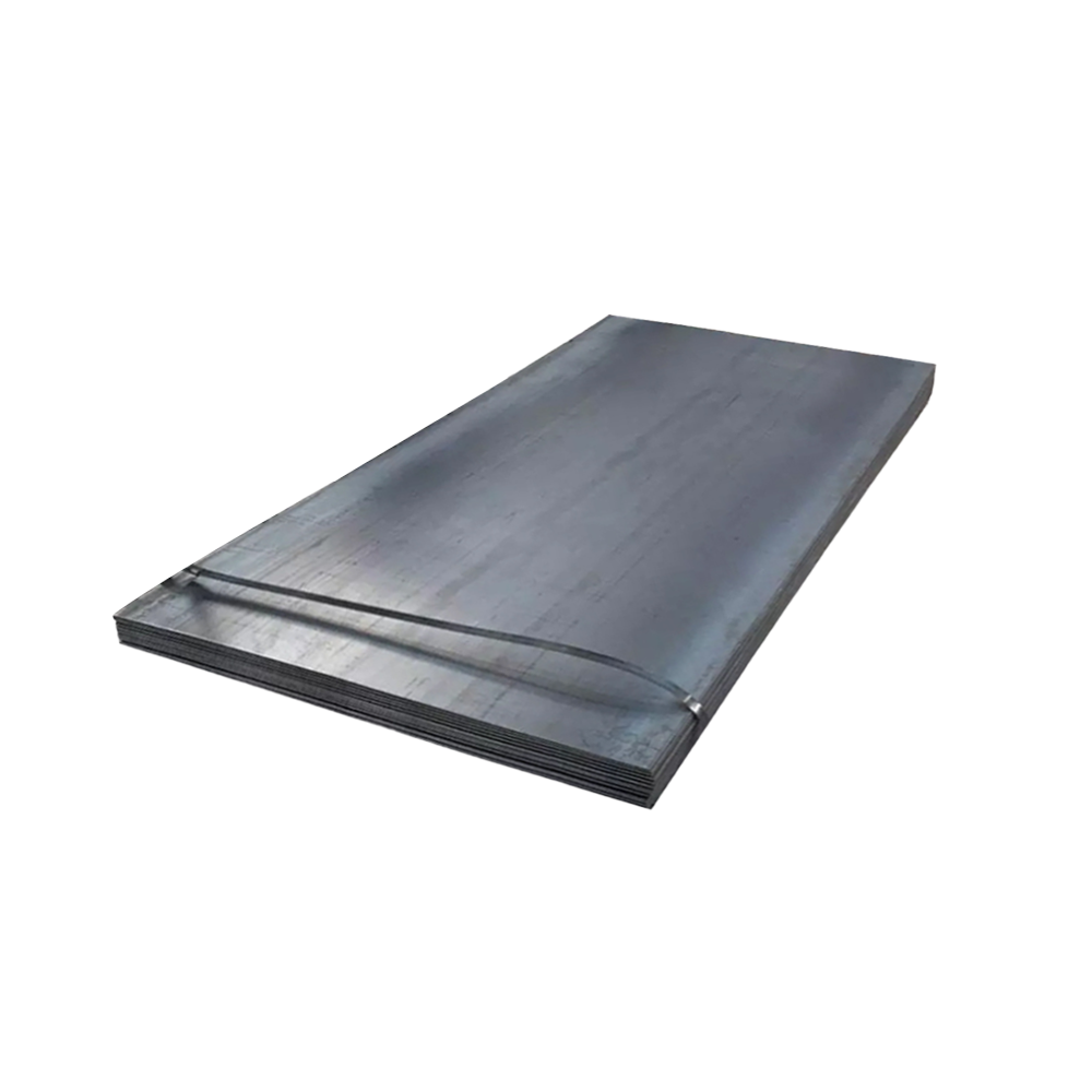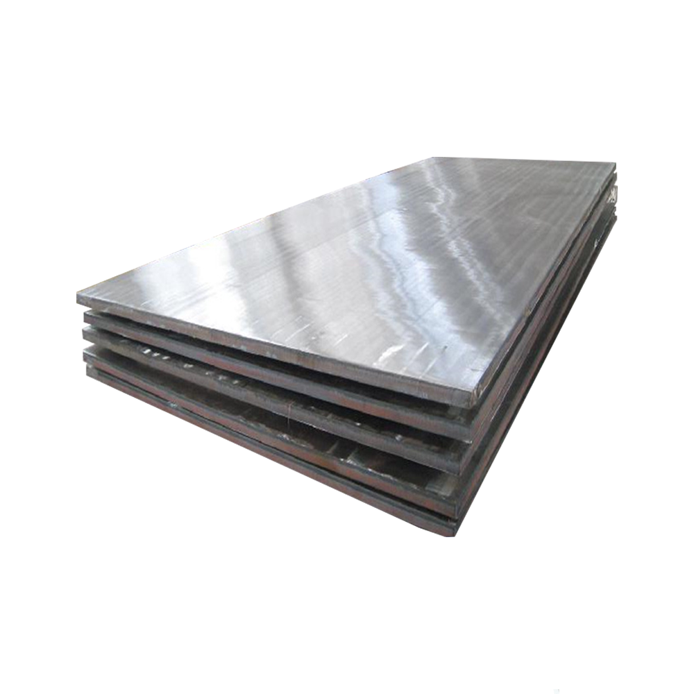
1. Material Composition & Manufacturing Process
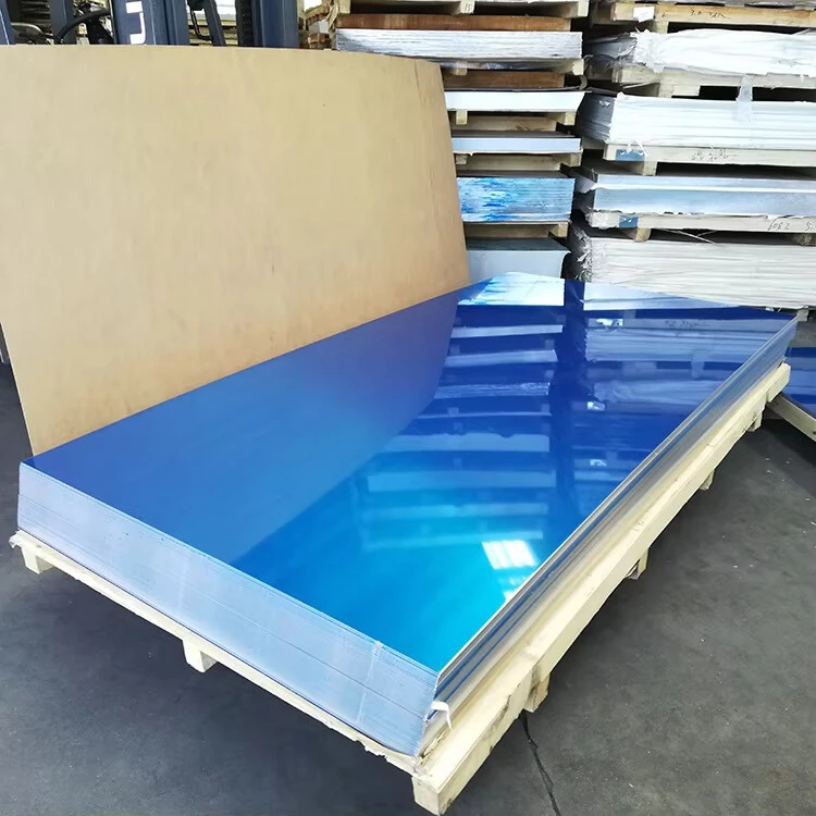
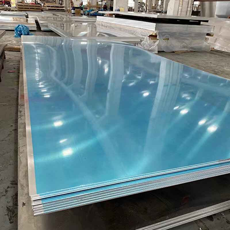
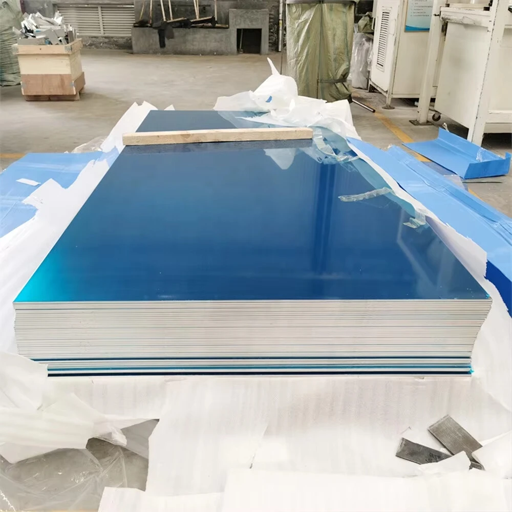
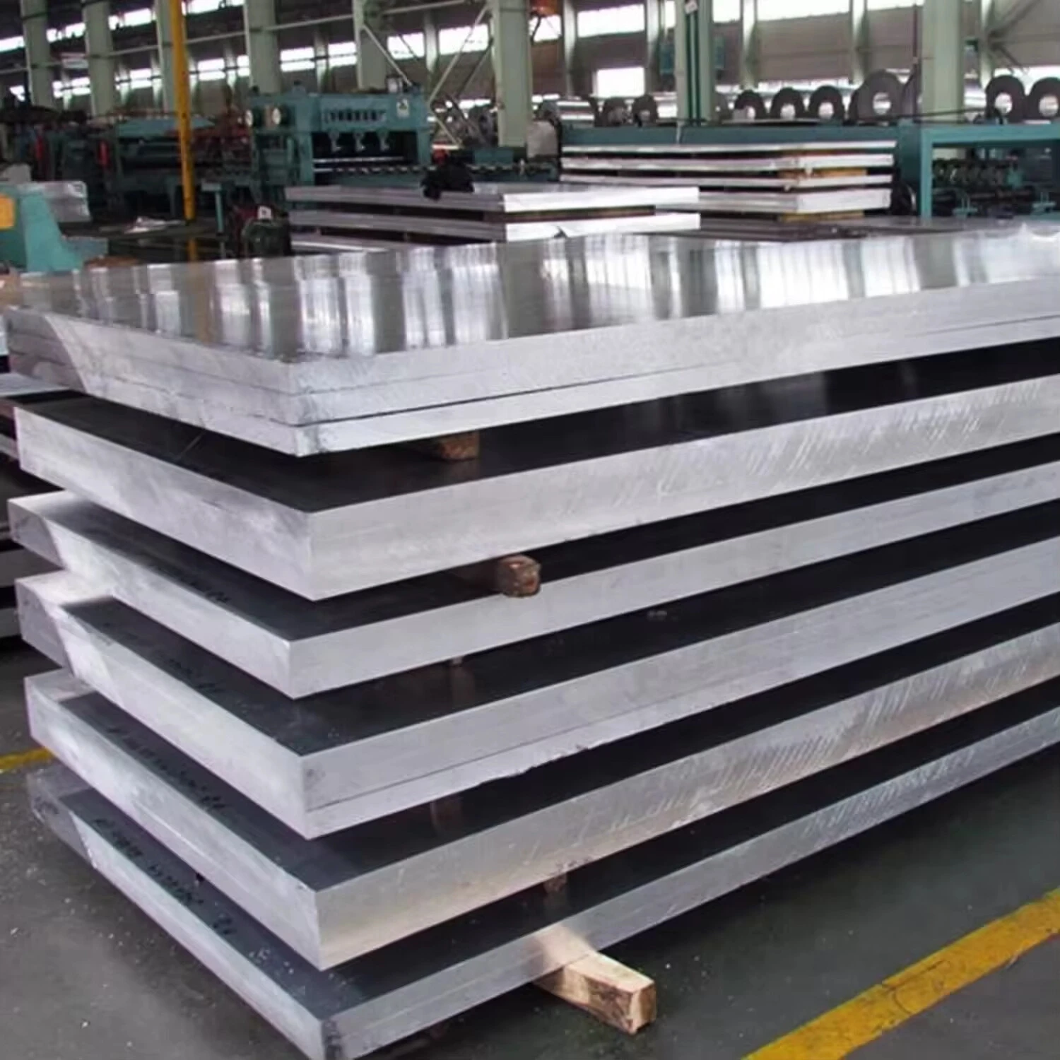
6061 aluminum alloy (ASTM B209, AMS 4025) is a heat-treatable Al-Mg-Si alloy engineered for versatility and excellent mechanical properties. Ultra-thick forged plate variants (>150mm) offer exceptional structural integrity through specialized manufacturing:
Alloy Chemistry:
Magnesium (Mg): 0.8-1.2% (Mg₂Si precipitation)
Silicon (Si): 0.4-0.8% (Mg₂Si formation)
Copper (Cu): 0.15-0.40% (strengthening)
Chromium (Cr): 0.04-0.35% (corrosion resistance)
Base Material:
Aluminum (Al): ≥97.5% (balance)
Controlled Impurities:
Iron (Fe): ≤0.7% max
Zinc (Zn): ≤0.25% max
Titanium (Ti): ≤0.15% max
Manganese (Mn): ≤0.15% max
Advanced Ultra-Thick Forging Process:
Ingot Casting: Premium double-degassed 7000-12000kg ingots
Pre-homogenization Inspection: Ultrasonic testing to Level A
Homogenization: 580-590°C for 24-36 hours (core temperature controlled)
Scalping: Surface machining to remove segregation zone
Preheating: Staged heating to 450-470°C with ±5°C uniformity
Open-Die Forging:
Multi-directional deformation
10,000-15,000 ton hydraulic press
Deformation ratio 3:1 minimum
Intermediate Annealing: 410°C for 6-8 hours when required
Solution Heat Treatment: 530-550°C for 2-5 hours (thickness dependent)
Precision Quenching: Polymer quench with controlled cooling rate 45-90°C/min
Straightening: Hydraulic press with distributed load
Artificial Aging: T6 or T651 temper at 170-190°C for 8-12 hours
Full quality documentation with melt-to-product traceability.
2. Mechanical Properties of Ultra-Thick Forged PlateProducts Description
| Property | Minimum | Typical | Test Standard | Significance for Ultra-Thick Sections |
| Ultimate Tensile Strength | 290 MPa | 310-330 MPa | ASTM B557 | Maintained through entire cross-section |
| Yield Strength (0.2% offset) | 240 MPa | 260-280 MPa | ASTM B557 | Less than 10% variation core to surface |
| Elongation (2 inch) | 8% | 10-14% | ASTM B557 | Critical for thick section ductility |
| Shear Strength | 170 MPa | 180-210 MPa | ASTM B769 | Joint design parameter for bolted connections |
| Bearing Strength (e/D=2.0) | 430 MPa | 450-480 MPa | ASTM E238 | Fastener hole performance |
| Fatigue Strength (10⁷) | 95 MPa | 100-120 MPa | ASTM E466 | Long-term cyclic loading resistance |
| Hardness (Brinell) | 95 HB | 95-105 HB | ASTM E10 | ≤5% variation through thickness |
| Fracture Toughness (K₁C) | 29 MPa√m | 32-37 MPa√m | ASTM E399 | Critical for damage tolerance |
| Through-Thickness Reduction | 6% min | 8-12% | ASTM E8 | Z-direction ductility |
Directionality (Typical Ratios):
L vs. LT: ≤1.05:1 tensile strength ratio
L vs. ST: ≤1.10:1 tensile strength ratio
Core vs. Surface: ≤1.08:1 yield strength ratio
3. Ultra-Thick Forging Microstructure ControlProducts Description
Thickness-Specific Processing:
Deformation Distribution:
Multi-axial forge compression
Minimum 25% reduction in final pass
Constant temperature control through section
Quench Rate Management:
Polymer concentration: 12-18%
Agitation velocity: 2.5-3.5 m/s
Temperature rise control: <15°C max
Thermal Gradient Mitigation:
Isothermal holds at critical temperatures
Core temperature monitoring during processing
Controlled cooling rate: 60-80°C/min surface, 40-55°C/min core
Microstructural Characteristics:
Grain Size: ASTM 4-6 (40-70μm)
Recrystallization: >85% recrystallized structure
Precipitate Distribution:
Primary Mg₂Si: 0.5-2μm
β” needles: 4-8nm in diameter
Q-phase and B’-phase controlled
Dispersoid Density: 1-3×10⁶/mm²
Texture: Modified cube with reduced anisotropy
Inclusion Rating: ≤0.5 per ASTM E45
Maximum Grain Size Variation: 2 ASTM numbers through thickness
4. Dimensional Specifications & Tolerances
| Parameter | Standard Range | Precision Tolerance | Commercial Tolerance |
| Thickness | 150-500 mm | ±3 mm | ±5 mm |
| Width | 1000-3500 mm | ±5 mm | ±8 mm |
| Length | 2000-12000 mm | +15/-0 mm | +25/-0 mm |
| Flatness | N/A | 0.15% of length | 0.30% of length |
| Parallelism | N/A | 0.5% of thickness | 1.0% of thickness |
| Edge Straightness | N/A | 1 mm/1000 mm | 2 mm/1000 mm |
| Surface Roughness | N/A | 6.3 μm Ra max | 12.5 μm Ra max |
Specialized Parameters:
Machining Allowance: 15mm per side recommended
Stress Relief: Required before precision machining
Ultrasonic Testing: 100% volumetric inspection
Density: 2.70 g/cm³ (±0.01 g/cm³)
Weight Formula: Thickness(mm) × Width(m) × Length(m) × 2.70 = Weight(kg)
Maximum Single Piece Weight: 25,000 kg
5. Heat Treatment & Property Optimization
| Temper Designation | Process | Applications | Key Properties |
| T651 | Solution treated, stress relieved by stretching (1.5-3%), artificial aging | Primary aerospace, defense, moldmaking | Maximum strength with good stress corrosion resistance |
| T6511 | Solution treated, stress relieved by stretching (controlled), artificially aged | Critical structural components, precision parts | Excellent dimensional stability with high strength |
| T6510 | Solution treated, minimal stress relief, artificially aged | Complex geometries, bridge components | Balanced properties with minimized distortion |
| T73 | Solution treated, overaged | High temperature service, stress corrosion critical applications | Superior stress corrosion resistance, thermal stability |
Solution Heat Treatment Parameters:
Temperature: 530-550°C
Time: 25 min/inch of thickness (minimum 2 hours)
Temperature Uniformity: ±5°C maximum variation
Quenching Delay: <15 seconds maximum
Transfer Equipment: Specialized handling fixtures
Artificial Aging Options:
T6 Cycle: 175-185°C for 8-10 hours
T651 Cycle: 175-185°C for 6-8 hours
T73 Cycle: Dual stage (175°C/4hr + 215°C/8hr)
6. Machining & Fabrication Characteristics
| Operation | Tool Material | Recommended Parameters | Notes for Ultra-Thick Plate |
| Heavy Milling | Carbide inserts | Vc=300-700 m/min, fz=0.15-0.25 mm | Climb milling preferred |
| Deep Hole Drilling | Carbide drills | Vc=60-120 m/min, fn=0.15-0.30 mm/rev | Peck cycle required |
| Boring | PCD tooling | Vc=500-1000 m/min | Dampened boring bars essential |
| Face Milling | Carbide face mills | Vc=350-800 m/min | High positive rake geometry |
| Tapping | HSS-E-PM taps | Vc=15-30 m/min | H-limits preferred |
| Sawing | Carbide-tipped | 40-60 m/min, 2-3 teeth engaged | Flood cooling mandatory |
Special Considerations:
Residual Stress Management: Release 75% of stock prior to final machining
Fixturing: Distributed clamping force to prevent distortion
Tool Engagement: Maximum 60% cutter diameter width of cut
Coolant: High-pressure (70+ bar) for deep features
Heavy Machining: Maximum 5mm depth of cut per pass
Heat Generation: Monitor workpiece temperature during machining
Chip Evacuation: Critical for deep pocket milling
7. Corrosion Resistance & Surface Treatmentson
| Environment | Performance | Protection Method | Service Life Expectation |
| Industrial Atmosphere | Very Good | Anodizing Type II/III | 15-20+ years |
| Marine Environment | Good | Chromate conversion + paint | 10-15+ years |
| Fresh Water | Excellent | Minimal protection needed | 30+ years |
| Chemical Processing | Fair to Good | PTFE impregnated anodize | Application specific |
| High Temperature | Fair | High-temperature coatings | 5-10+ years |
| Buried Service | Very Good | Bituminous coatings | 40+ years |
Surface Treatment Options:
Anodizing:
Type II: 10-25μm thickness
Type III (Hard): 25-75μm thickness
PTFE impregnated options
Conversion Coatings:
Chromate conversion (MIL-DTL-5541)
Trivalent chromium treatments
Non-chromate alternatives (Ti/Zr based)
Painting Systems:
Epoxy primer + polyurethane topcoat
Powder coating (190-210°C cure)
High-solids industrial coatings
Special Surface Preparations:
Mechanical: Grit blast Sa 2.5
Chemical: Acid etch and desmut
Laser texturing for specialized applications
8. Physical Properties for Design Engine
ering
| Property | Value | Significance in Ultra-Thick Applications |
| Density | 2.70 g/cm³ | Weight calculation for large components |
| Melting Range | 582-652°C | Stress relieving limitations |
| Thermal Conductivity | 167 W/m·K | Heat dissipation in large masses |
| Electrical Conductivity | 43% IACS | EMI shielding applications |
| Specific Heat | 896 J/kg·K | Thermal inertia in processing |
| Thermal Expansion | 23.6 ×10⁻⁶/K | Differential expansion in assemblies |
| Young’s Modulus | 68.9 GPa | Stiffness in structural applications |
| Poisson’s Ratio | 0.33 | Dimensional changes under load |
| Damping Capacity | 0.008-0.01 | Vibration characteristics |
| Thermal Diffusivity | 69 mm²/s | Processing heat transfer rate |
9. Quality Control & Testing Protocols
Mandatory Testing Protocol:
Chemical Analysis: Optical emission spectroscopy
Mechanical Testing:
Tensile testing (surface, t/4, t/2 positions)
Hardness survey (traverse and longitudinal)
Non-Destructive Evaluation:
Ultrasonic inspection per AMS-STD-2154 Class A
Penetrant inspection of critical surfaces
Metallurgical Evaluation:
Grain size measurement per ASTM E112
Inclusion rating per ASTM E45
Microstructural analysis for precipitate distribution
Dimensional Inspection:
CMM verification of critical dimensions
Laser scanning for profile accuracy
Thickness mapping at defined grid points
Certification Package:
Material Test Report (EN 10204 Type 3.1/3.2)
Chemical composition certificate
Mechanical property certification
Heat treatment chart records
NDT reports and acceptance criteria
Dimensional inspection reports
Traceability documentation (melt to product)
Compliance declarations (RoHS, REACH, etc.)
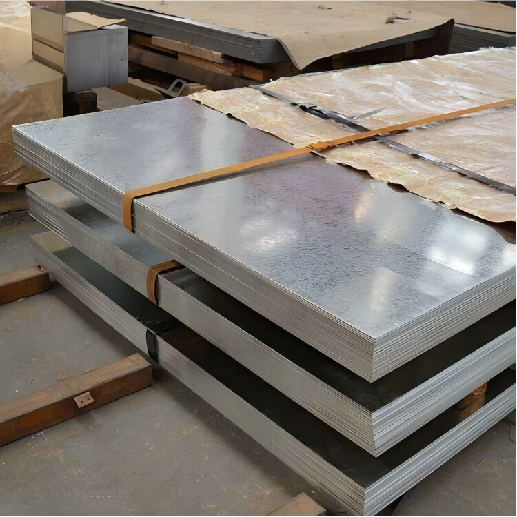
10. Industrial Applications & Handling
Primary Applications:
Aerospace structural components
Defense system platforms
Semiconductor manufacturing equipment
Plastic injection mold bases
Bridge structural elements
Nuclear industry components
Heavy transportation frames
Machine tool structural bases
Rolling mill backup rolls
High-strength fixturing elements
Material Handling Protocol:
Lifting Requirements:
Minimum 4-point lifting system
Spreader bars mandatory
Maximum sling angle: 60° from horizontal
Lifting capacity: Safety factor of 3:1
Storage Conditions:
Indoor storage recommended
Support at minimum 300mm intervals
Stacking height limitation: 1.5m maximum
Avoid direct contact with dissimilar metals
Transportation:
Secure with non-metallic strapping
Vibration dampening materials
Edge protection mandatory
Moisture protection during transit
Machining Preparation:
Temperature stabilization: 24 hours minimum
Stress relieving recommended before critical machining
Sequential material removal plan
Progressive clamping force adjustment
11. Design Considerations for Ultra-Thick Sections
Structural Design Factors:
Section Modulus Optimization:
Utilize full thickness advantage for bending resistance
I-beam equivalent performance with reduced weight
Consider internal web structures in very thick sections
Fastener Selection:
Minimum edge distance: 2× bolt diameter
Recommended thread engagement: 1.5× bolt diameter
Torque specifications: 65-75% of standard steel values
Bearing strength utilization up to 480 MPa
Thermal Management:
Allow for thermal expansion of 2.36mm per meter per 100°C
Design expansion joints for large structures
Consider thermal gradients during welding
Dynamic Loading:
Fatigue endurance limit approximately 100 MPa
Apply stress concentration factors at design phase
Shot peening for fatigue-critical surfaces
Weight Reduction Strategies:
Pocket milling of non-critical areas
Selective thickness distribution
Hybrid structures with composite elements
Topology optimization for