1. Material Composition & Manufacturing Process
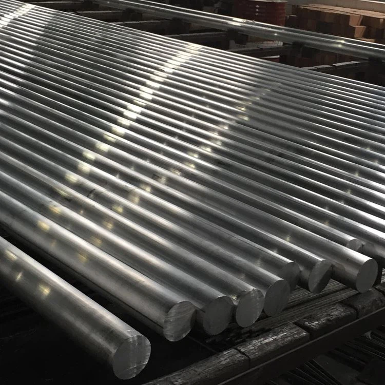
7075-T6 aluminum round bar represents the pinnacle of high-strength aluminum alloys, offering an exceptional combination of strength, hardness, and stress resistance for aerospace, defense, and high-performance mechanical applications:
Primary Alloying Elements:
Zinc (Zn): 5.1-6.1% (principal strengthening element)
Magnesium (Mg): 2.1-2.9% (enhances precipitation hardening)
Copper (Cu): 1.2-2.0% (improves strength and stress resistance)
Chromium (Cr): 0.18-0.28% (corrosion resistance and grain structure control)
Base Material:
Aluminum (Al): ≥87.1% (balance)
Controlled Impurities:
Iron (Fe): ≤0.50% max
Silicon (Si): ≤0.40% max
Manganese (Mn): ≤0.30% max
Titanium (Ti): ≤0.20% max
Other elements: ≤0.05% each, ≤0.15% total
Premium Manufacturing Process:
Melt Preparation:
Primary high-purity aluminum (99.7% minimum)
Precise alloying element additions with ±0.1% tolerance
Advanced filtration through ceramic foam filters (30-40 ppi)
SNIF degassing treatment (hydrogen < 0.10 ml/100g)
Grain refinement with Al-Ti-B master alloy
Direct-chill (DC) semi-continuous casting
Homogenization:
460-480°C for 24-48 hours
Uniform temperature control: ±5°C
Controlled cooling rate: 20-30°C/hour
Dissolution of coarse intermetallics
Microsegregation elimination
Hot Working Process:
Breakdown forging/rolling: 385-415°C
Intermediate operations: 370-400°C
Final hot working: 350-380°C
Computerized temperature monitoring throughout
Solution Heat Treatment:
465-485°C for 1-2 hours (diameter dependent)
Temperature uniformity: ±3°C
Rapid transfer to quenching medium
Maximum transfer time: 10 seconds
Quenching:
Cold water (10-30°C)
Agitation for uniform cooling
Minimum cooling rate: 100°C/sec at surface
Cold Stretching (T651):
1.5-3.0% permanent deformation
Stress relief and straightening
Dimensional accuracy enhancement
Artificial Aging (T6):Dual-stage aging process:
First stage: 110-130°C for 4-6 hours
Second stage: 165-175°C for 8-12 hours
Temperature uniformity: ±3°C
Controlled cooling after aging
Final Processing:
Precision centerless grinding (optional)
Stress-free straightening
Nondestructive testing
Surface treatment and protection
Full process traceability with computerized quality monitoring at all stages.
2. Mechanical Properties of 7075-T6 Aluminum Round Bar
| Property | Minimum | Typical Range | Test Method |
| Ultimate Tensile Strength | 570 MPa | 580-600 MPa | ASTM E8 |
| Yield Strength (0.2%) | 500 MPa | 510-540 MPa | ASTM E8 |
| Elongation (2 inch) | 7% | 8-11% | ASTM E8 |
| Hardness (Brinell) | 150 HB | 155-165 HB | ASTM E10 |
| Fatigue Strength (5×10⁸) | 160 MPa | 170-190 MPa | ASTM E466 |
| Shear Strength | 330 MPa | 340-360 MPa | ASTM B769 |
| Fracture Toughness (K₁c) | 24 MPa√m | 25-29 MPa√m | ASTM E399 |
| Compressive Yield Strength | 520 MPa | 530-550 MPa | ASTM E9 |
| Modulus of Elasticity | 71.7 GPa | 71.7-72.4 GPa | ASTM E111 |
Property Distribution:
Longitudinal to transverse property ratio: 1.00:0.95 (strength), 1.00:0.75 (elongation)
Variation across diameter: <5% for diameters up to 75mm, <8% for diameters >75mm
Core to surface hardness variation: <10 HB for diameters up to 100mm
Property stability: <3% strength reduction after 10,000 hours at 100°C
Stress Corrosion Cracking Threshold: 125-175 MPa (dependent on environment)
3. Microstructural Characteristics
Key Microstructural Features:
Grain Structure:
Partially recrystallized structure with elongated grains
ASTM grain size 7-9 (32-16μm)
Aspect ratio: 2:1 to 4:1 (length:width)
Well-controlled grain flow pattern
Precipitate Distribution:
MgZn₂ (η/η’) strengthening precipitates: 5-15nm
CuMgAl₂ (S-phase) precipitates
Al₇Cu₂Fe intermetallics: Controlled size and distribution
Al₁₂Mg₂Cr dispersoids: 50-200nm
Texture Development:
Strong <111> and <100> fiber textures
Texture intensity: 3-8× random
Optimized for maximum strength in primary loading directions
Special Features:
Precipitation-hardened microstructure
Minimal precipitate-free zones (PFZs) at grain boundaries
Controlled distribution of coarse intermetallics
Fine dispersoid distribution for recrystallization control
4. Dimensional Specifications & Tolerances
| Parameter | Standard Range | Precision Tolerance | Commercial Tolerance | Test Method |
| Diameter | 10-250 mm | ±0.10mm up to 30mm | ±0.20mm up to 30mm | Micrometer |
| ±0.4% above 30mm | ±0.7% above 30mm | |||
| Ovality | N/A | 50% of diameter tolerance | 75% of diameter tolerance | Micrometer |
| Length | 2000-6000 mm | ±2mm | ±5mm | Tape measure |
| Straightness | N/A | 0.2mm/m | 0.5mm/m | Straightedge |
| Surface Roughness | N/A | 1.6 μm Ra max | 3.2 μm Ra max | Profilometer |
| Cut End Squareness | N/A | 0.5° max | 1.0° max | Protractor |
Standard Available Forms:
Diameters: 10mm to 250mm (larger sizes available on request)
Standard Lengths: 2000mm, 3000mm, 4000mm, 6000mm
Custom cut lengths available
Centerless ground bars available for precision applications
Saw-cut ends with protective end caps
5. Temper Designations & Heat Treatment Options
| Temper Code | Process Description | Optimal Applications | Key Characteristics |
| T6 | Solution heat treated and artificially aged | High-strength applications | Maximum strength and hardness |
| T651 | T6 + stress relieved by stretching | Critical aerospace components | Improved stress corrosion resistance |
| T73 | Overaged for stress corrosion resistance | Corrosion-critical applications | Better SCC resistance with reduced strength |
| T76 | Modified overaging treatment | Balanced properties | Compromise between T6 and T73 |
| T7351 | T73 + stress relieved by stretching | Thick sections with residual stress concerns | Dimensional stability with SCC resistance |
Temper Selection Guidance:
T6/T651: Highest strength requirements
T73/T7351: Stress-corrosion critical applications
T76: Balanced properties for general aerospace applications
6. Machining & Fabrication Characteristics
| Operation | Tool Material | Recommended Parameters | Comments |
| Turning | Carbide, PCD | Vc=150-300 m/min, f=0.1-0.3 mm/rev | Sharp tools essential |
| Drilling | HSS-Co, Carbide | Vc=60-120 m/min, f=0.15-0.35 mm/rev | Frequent chip clearing |
| Milling | Carbide, PCD | Vc=180-350 m/min, fz=0.05-0.15 mm | Climb milling preferred |
| Tapping | HSS-Co, TiN coated | Vc=10-20 m/min | Thread quality sensitive to heat |
| Reaming | Carbide, PCD | Vc=40-90 m/min, f=0.1-0.3 mm/rev | H7 tolerance achievable |
| Thread Milling | Carbide | Vc=100-200 m/min, fz=0.03-0.08 mm | Preferred over tapping for critical threads |
Fabrication Guidance:
Machinability Rating: 70% (1100 aluminum = 100%)
Surface Finish: Good (Ra 0.8-3.2μm achievable)
Chip Formation: Short to medium chips with proper tooling
Coolant: Water-soluble emulsion preferred (8-10% concentration)
Tool Wear: Moderate with proper parameters
Cutting Forces: Higher than other aluminum alloys
Weldability: Poor (not recommended for structural applications)
Cold Working: Limited formability
Hot Working: Not recommended in T6 condition
Heat Treatment: Can be fully re-heat treated after machining
7. Corrosion Resistance & Protection Systems
| Environment Type | Resistance Rating | Protection Method | Expected Performance |
| Industrial Atmosphere | Fair | Anodizing + paint | 3-5 years with maintenance |
| Marine Environment | Poor | Anodizing + chromate + paint | 2-3 years with maintenance |
| High Humidity | Fair | Anodizing Type II | 1-2 years without additional protection |
| Stress Corrosion | Poor in T6, Good in T73 | Proper temper selection | Application specific |
| Exfoliation | Poor | Proper temper + protection | Critical in marine applications |
| Galvanic Corrosion | Poor with carbon steels | Isolation or sacrificial protection | Requires careful design |
Surface Protection Options:
Anodizing:
Type I (Chromic): 2-8μm (aerospace grade)
Type II (Sulfuric): 10-25μm (general purpose)
Type III (Hard): 25-75μm (wear resistance)
Sealing options: Hot water, dichromate, nickel acetate
Conversion Coatings:
Chromate per MIL-DTL-5541 Class 1A
Non-chromium alternatives for environmental compliance
Painting Systems:
Epoxy primer + polyurethane topcoat
Aerospace-qualified systems available
Mechanical Protection:
Shot peening for enhanced fatigue and SCC resistance
Glass bead blasting for uniform appearance
8. Physical Properties for Engineering Design
| Property | Value | Design Consideration |
| Density | 2.81 g/cm³ | Weight calculation for components |
| Melting Range | 477-635°C | Heat treatment limitations |
| Thermal Conductivity | 130-150 W/m·K | Thermal management design |
| Electrical Conductivity | 33-40% IACS | Electrical applications design |
| Specific Heat | 860 J/kg·K | Thermal mass calculations |
| Thermal Expansion (CTE) | 23.4 ×10⁻⁶/K | Thermal stress analysis |
| Young’s Modulus | 71.7 GPa | Deflection and stiffness calculations |
| Poisson’s Ratio | 0.33 | Structural analysis parameter |
| Magnetic Permeability | ~1.00 (non-magnetic) | Electronic applications |
Design Considerations:
Operating Temperature Range: -70°C to +120°C
Property Retention: Excellent below 100°C, gradual degradation above
Stress Relaxation: Minimal below 100°C
Fatigue Life: Superior to most aluminum alloys
Notch Sensitivity: Moderate to high
Cryogenic Performance: Good strength retention at low temperatures
Vibration Damping: Poor (typical of high-strength aluminum)
9. Quality Assurance & Testing
Standard Testing Procedures:
Chemical Composition:
Optical emission spectroscopy
X-ray fluorescence analysis
Verification of all major elements and impurities
Mechanical Testing:
Tensile testing (longitudinal and transverse)
Hardness testing (Brinell, Rockwell B)
Impact testing (when required)
Fatigue testing (for critical applications)
Dimensional Inspection:
Diameter/ovality at multiple locations
Straightness verification
Length measurement
Nondestructive Testing:
Ultrasonic inspection per AMS-STD-2154
Eddy current testing for surface defects
Penetrant inspection (critical applications)
Microstructural Analysis:
Grain size determination
Intermetallic particle evaluation
Exfoliation corrosion susceptibility (ASTM G34)
Standard Certifications:
Mill Test Report (EN 10204 3.1)
Chemical analysis certification
Mechanical properties certification
Heat treatment certification
Nondestructive testing certification
Material traceability documentation
10. Applications & Design Considerations
Primary Applications:
Aerospace Components:
Aircraft landing gear components
Wing spars and structural elements
Fuselage frames and bulkheads
Engine mounts and supports
Defense Applications:
Missile components
Weapons systems parts
Armored vehicle components
Tactical equipment fixtures
High-Performance Automotive:
Drive shafts
Suspension components
Connecting rods
Performance-critical fasteners
Industrial Equipment:
High-stress machine parts
Molds for plastic injection
Hydraulic system components
Robotics and automation components
Specialized Applications:
Precision instrument components
High-performance sporting equipment
Rock climbing equipment
Camera mounting systems
Design Advantages:
Exceptional strength-to-weight ratio
Superior fatigue performance
High resistance to mechanical wear
Excellent machining characteristics
Dimensional stability after machining
Reliable performance in high-stress applications
Comprehensive material database for engineering design
Wide availability in standard sizes

