1. Material Composition & Manufacturing Process
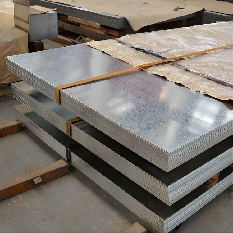
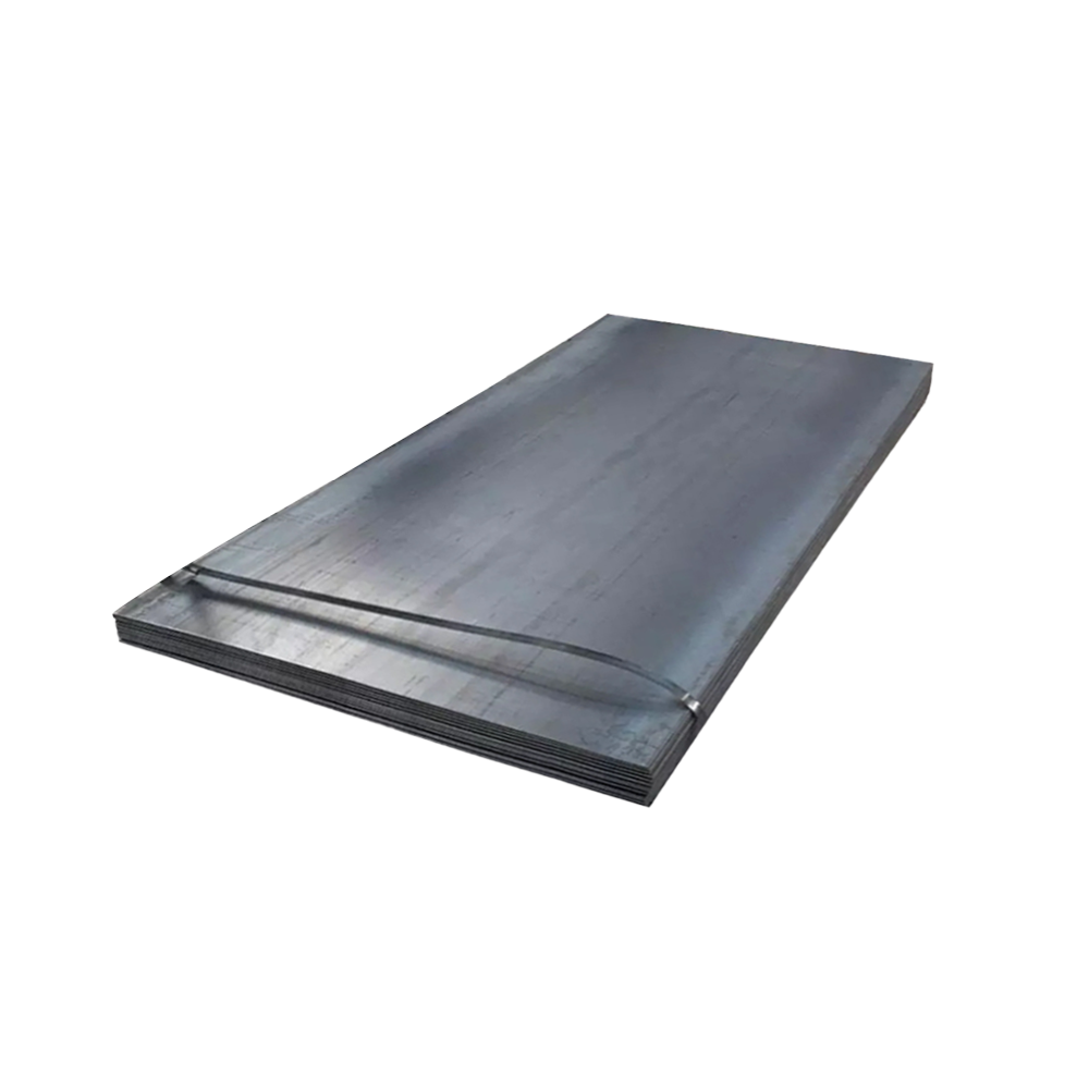
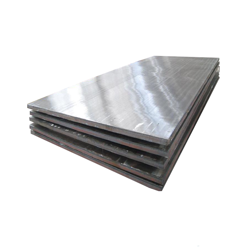
7075 aluminum alloy (AMS 4045, ASTM B247) represents a premium high-strength aerospace material optimized for critical aircraft structural components. The ultra-thick forged plate variant provides exceptional strength-to-weight performance through specialized processing:
Primary Alloying Elements:
Zinc (Zn): 5.1-6.1% (primary strengthening element)
Magnesium (Mg): 2.1-2.9% (precipitation hardening)
Copper (Cu): 1.2-2.0% (strength enhancement)
Chromium (Cr): 0.18-0.28% (corrosion resistance)
Base Material:
Aluminum (Al): ≥87.1% (balance)
Controlled Impurities:
Iron (Fe): ≤0.50% max
Silicon (Si): ≤0.40% max
Manganese (Mn): ≤0.30% max
Titanium (Ti): ≤0.20% max
Ultra-Thick Forging Process:
Premium Ingot Production:
Vacuum-degassed primary aluminum
Triple filtration through ceramic filters
Direct-chill (DC) casting with controlled cooling
Homogenization Treatment:
460-480°C for 24-48 hours (thickness-dependent)
Computer-controlled thermal profiles
Surface Conditioning:
Scalping minimum 12mm per surface
Ultrasonic inspection for internal quality
Multi-directional Forging:
Initial breakdown: 410-430°C
Final forging: 360-380°C
Deformation ratio: 4:1 minimum
Multi-directional working for optimal isotropy
Solution Heat Treatment:
465-480°C for thickness-specific duration
Computer-monitored temperature uniformity
Quenching:
Polymer quenchant with controlled concentration
Agitation rate: 3-5 m/s minimum
Core cooling rate: >50°C/sec minimum
Controlled Stretching:
1.5-3.0% permanent deformation
Artificial Aging:
T651/T7351 tempers: Multi-stage aging cycle
Temperature control: ±2°C maximum deviation
All processing maintains complete traceability with digital monitoring throughout manufacturing.
2. Mechanical Properties of Ultra-Thick 7075 Forged Plate
| Property | Minimum (T651) | Typical (T651) | Test Standard |
| Ultimate Tensile Strength | 530 MPa | 565-590 MPa | ASTM E8/E8M |
| Yield Strength (0.2%) | 455 MPa | 495-520 MPa | ASTM E8/E8M |
| Elongation (2 inch) | 7% | 9-12% | ASTM E8/E8M |
| Fracture Toughness (K₁c) | 26 MPa√m | 28-31 MPa√m | ASTM E399 |
| Shear Strength | 330 MPa | 340-360 MPa | ASTM B769 |
| Bearing Strength (e/D=2.0) | 785 MPa | 800-850 MPa | ASTM E238 |
| Fatigue Strength (10⁷) | 160 MPa | 170-190 MPa | ASTM E466 |
| Hardness (Brinell) | 140 HB | 145-155 HB | ASTM E10 |
Through-Thickness Performance:
Property variation <8% between surface and core (up to 250mm thickness)
Directionality ratio (L:LT:ST): 1.00:0.95:0.85 for tensile strength
Core-to-surface hardness variation: ≤10 HB maximum
3. Microstructural Engineering for Ultra-Thick Sections
Critical Processing Parameters:
Grain Structure Control:
Unrecrystallized, fibrous grain morphology
Cr-dispersoid pinning of grain boundaries
Specialized thermal profile for thick sections
Precipitate Engineering:
MgZn₂ (η/η’) precipitate size: 5-15nm
Al₂CuMg (S-phase) distribution
Al₇Cu₂Fe intermetallic control
Quench Rate Optimization:
Polymer concentration: 12-18%
Agitation system: Multi-directional high-velocity flow
Minimum center cooling rate: 55°C/sec
Microstructural Characteristics:
Grain Size: ASTM 8-10 (15-30μm)
Grain Aspect Ratio: 3:1 to 5:1 (L:ST)
Recrystallized Volume Fraction: <15% maximum
Precipitate Density: >10¹⁷/cm³
Inclusion Rating: ≤0.3 per ASTM E45
4. Dimensional Specifications & Tolerances
| Parameter | Standard Range | Aerospace Tolerance | Commercial Tolerance |
| Thickness | 100-300 mm | ±0.8mm or ±0.5%* | ±1.5mm or ±1.0%* |
| Width | 1000-2500 mm | ±3 mm | ±6 mm |
| Length | 2000-8000 mm | ±5 mm | ±12 mm |
| Flatness | N/A | 0.1% of length | 0.3% of length |
| Parallelism | N/A | 0.2% of thickness | 0.5% of thickness |
| Surface Roughness | N/A | 3.2 μm Ra max | 6.3 μm Ra max |
*Whichever is greater
Ultra-Thick Specific Parameters:
Density: 2.81 g/cm³ (±0.02)
Weight Formula: Thickness(mm) × Width(m) × Length(m) × 2.81 = Weight(kg)
Machining Allowance: Recommend 15mm per side for critical dimensions
Ultrasonic Testing: 100% volumetric inspection per AMS-STD-2154 Class A
5. Heat Treatment & Temper Options
| Temper Designation | Process Details | Optimized Properties | Target Applications |
| T651 | Solution heat treated, stretched (1.5-3%), artificially aged | Maximum strength | Primary aircraft structures |
| T7351 | Solution heat treated, stretched, overaged | Improved SCC resistance, better toughness | Critical aerospace components |
| T7651 | Solution heat treated, stretched, specially overaged | Balanced strength and SCC resistance | Wing structures |
Heat Treatment Parameters:
Solution Heat Treatment:
Temperature: 465-480°C
Time: 1 hour per 25mm thickness (minimum)
Quench Delay: <12 seconds maximum
Artificial Aging:
T651: 120°C for 24 hours
T7351: 115°C for 6-8 hours + 175°C for 8-16 hours
Temperature Tolerance: ±2°C
6. Machining & Manufacturing Considerations
| Operation | Tool Material | Recommended Parameters | Considerations for Ultra-Thick Plate |
| Roughing | Carbide | Vc=300-600 m/min, fz=0.1-0.3 mm | Step-down approach, progressive depth |
| Finishing | PCD/CBN inserts | Vc=600-1200 m/min | Light cuts, high surface speed |
| Deep Hole Drilling | Carbide coolant-fed | Vc=60-120 m/min, fn=0.1-0.3 mm/rev | Peck drilling essential |
| Face Milling | PCD/Carbide | Vc=500-1000 m/min | Positive rake geometry |
Manufacturing Best Practices:
Cutting Fluids: Water-soluble coolant with pH 8.5-9.5
Chip Management: High-pressure coolant for evacuation
Fixturing: Distributed clamping to minimize distortion
Cutting Strategy: Climb milling for optimal surface finish
Residual Stress Management: Rough machine, stress relieve, finish machine
7. Corrosion Resistance & Protection Systems
| Environment Type | Resistance Rating | Protection Method | Service Life Expectation |
| Industrial Atmosphere | Moderate | Anodizing + primer/topcoat | 8-12 years with maintenance |
| Marine Environment | Poor-Fair | Anodizing + chromated primer + topcoat | 5-8 years with maintenance |
| Stress Corrosion | Good (T7 tempers) | Overaging + surface compression | Significant improvement over T6 |
| Exfoliation | Good (T7 tempers) | Proper heat treatment | EXCO rating of EA or better |
Surface Treatment Options:
Anodizing:
Type II (Sulfuric): 10-25μm
Type III (Hard): 25-75μm
Chromic: 2-8μm for maximum fatigue performance
Conversion Coatings:
Chromate per MIL-DTL-5541 Class 1A
Trivalent chromium pretreatment
Paint Systems:
High-solids epoxy primer
Polyurethane topcoat
Mechanical Surface Enhancement:
Shot peening (0.008-0.012A intensity)
Laser shock peening
8. Physical Properties for Engineering Design
| Property | Value | Design Significance |
| Density | 2.81 g/cm³ | Weight calculations for aircraft structures |
| Melting Range | 477-635°C | Welding/heat treatment limitations |
| Thermal Conductivity | 130-150 W/m·K | Heat dissipation in high-load components |
| Electrical Conductivity | 33-40% IACS | EMI shielding applications |
| Specific Heat | 960 J/kg·K | Thermal mass calculations |
| Thermal Expansion (CTE) | 23.4 ×10⁻⁶/K | Thermal stress predictions |
| Young’s Modulus | 71.7 GPa | Structural stiffness in airframe design |
| Poisson’s Ratio | 0.33 | Critical for FEA modeling |
Special Considerations for Ultra-Thick Sections:
Residual Stress Distribution: Through-thickness mapping required
Thermal Inertia: Slow response to temperature changes
Deep Hardenability: Consistent properties through section
9. Quality Assurance & Testing Protocols
Mandatory Inspection Regime:
Chemical Composition:
Optical emission spectroscopy
Verification of all major elements and impurities
Mechanical Testing:
Full tensile test (L, LT, ST directions)
K₁c fracture toughness testing
Hardness survey (25mm grid minimum)
Non-Destructive Testing:
Ultrasonic inspection per AMS-STD-2154 Class A
Penetrant inspection of critical surfaces
Microstructural Analysis:
Grain size and morphology
Inclusion rating per ASTM E45
Certification Documentation:
Material Test Report (MTR) per EN 10204 3.1/3.2
Chemical analysis certification
Mechanical properties certification
Heat treatment chart records
NDT reports with acceptance criteria
10. Applications & Performance Advantages
Primary Aerospace Applications:
Bulkhead structures
Wing spars and carry-through structures
Landing gear components
Fuselage frames and longerons
Thick section structural members
Upper wing skins
High-load fittings
Performance Advantages for Ultra-Thick Sections:
Uniform properties throughout thickness
Superior damage tolerance
Enhanced stress corrosion resistance in T7 tempers
Improved through-thickness strength
Superior machinability in thick sections
Consistent quality through rigorous processing controls